MADCAT Smart Nerf Gun
Our team designed a project and wrote a proposal to create the MADCAT (Management for Ammunition and Data Collection About Target) Smart Nerf Gun. Once our project was approved by our instructors, we were in charge of all aspects of design, software development, and hardware assembly.
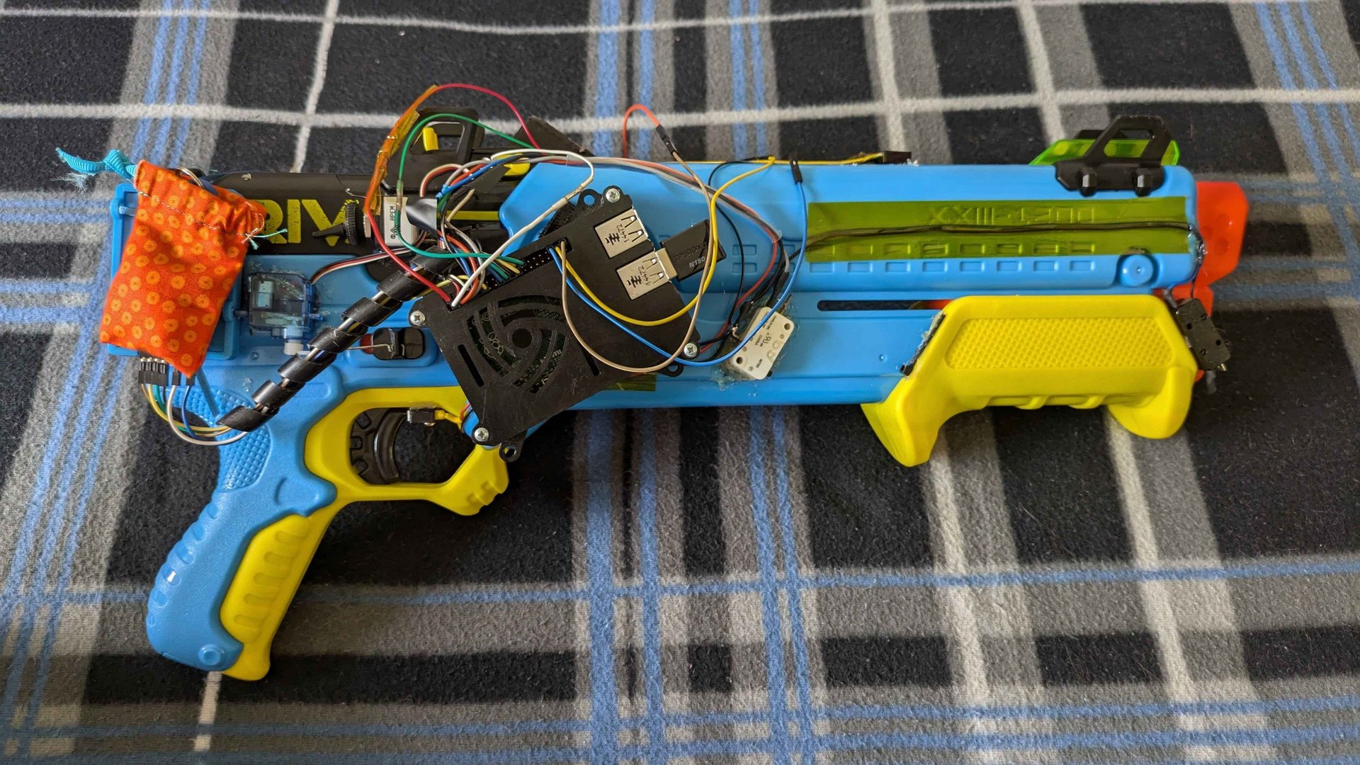
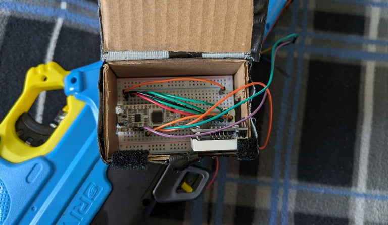
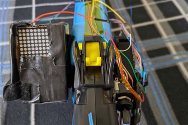
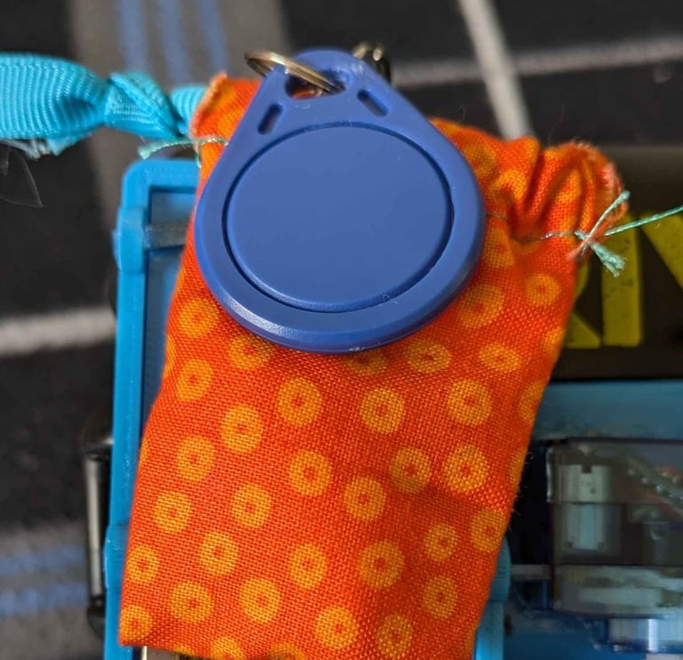
We designed a smart Nerf gun with a 12-ammo capacity. The gun requires a special RFID Key to activate and the program will lock the trigger if the key is not in its pouch on the gun. This gun also keeps track of ammo using an IR sender/receiver where ammo is loaded and a switch on the trigger. The ammo count is displayed on an LED Matrix Display. This matrix flashes a red 0 on the display if there is no ammo left in the gun. An STM32 board governs the ammo-count display mechanism and a Raspberry Pi 2.
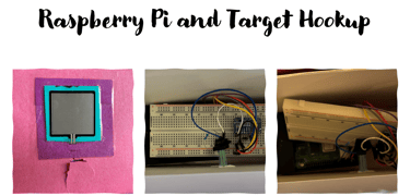
The Nerf gun comes with a target that contains a Raspberry Pi. That Raspberry Pi is connected via UDP to another Raspberry Pi located on the Nerf gun. The target Pi keeps track of total foam rounds fired, total times the target has been hit, and an accuracy percentage, while the gun is in “target fire” mode. Otherwise, the gun is in “free-fire” mode. In free-fire mode, the Raspberry Pi simply records foam rounds fired. A switch on the gun allows the user to change modes. The gun code will tell a Bluetooth speaker to make different sounds depending on whether the target has been hit or missed.
This project was coded in python on each Raspberry Pi and in C for the STM 32. All of the boards were getting input from different sensors and communicating those inputs with other boards either through hardwiring to a pin on the STM 32 or sending data over the UDP between the 2 Raspberry Pis.

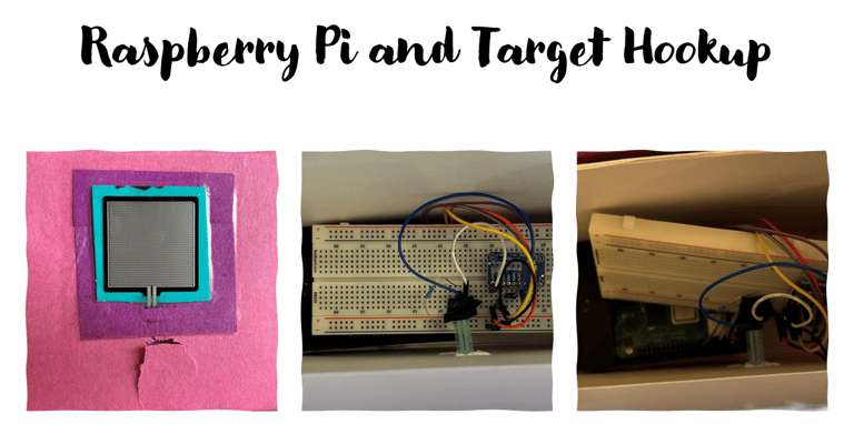
Force Sensor on the Target:
The target uses a force sensor to detect when it has been hit. The force sensor is hooked up to an ADC and the ADC output is read by the Raspberry Pi via I2C. In the code, a pressure threshold was set and used to track how many times the target was hit at different thresholds. This threshold was initially tested at 1000, 2000, and 3000 with a different output for when the different thresholds were hit. In the final code, the pressure threshold was set to 1000 so there would be no issues detecting a hit from the gun but not sending a signal if moved. This is the only electrical or mechanical not on the gun with the exception of the bluetooth speaker the target Raspberry Pi sends sounds to.
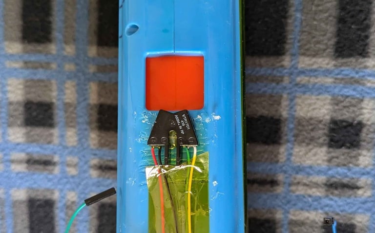
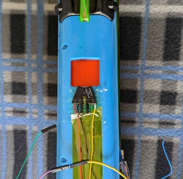
Ammo Tracking IR Sensor:
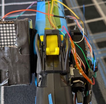
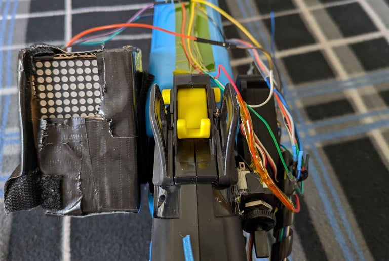
There is an IR transmitter and receiver on the gun itself to detect when ammo is put into the gun and when a shot is fired. The way ammo is loaded into the nerf gun and how the gun uses air pressure to fire did not allow for any internal switches or sensors for ammo tracking capabilities. One way to get around this issue was by adding an IR sensor. When a person loads a ball into the gun, the IR sensor will detect the light bouncing off the ball and send a signal to the STM 32 which handles the ammo tracking. This sensor is located on the gun slightly behind where the ammo is loaded in from on the top of the gun on the side closer to the user.
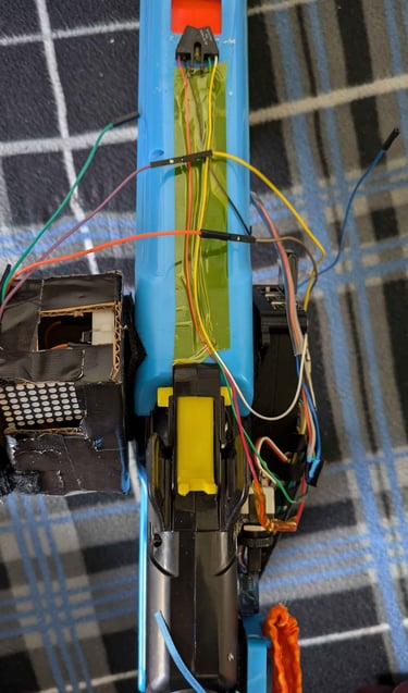
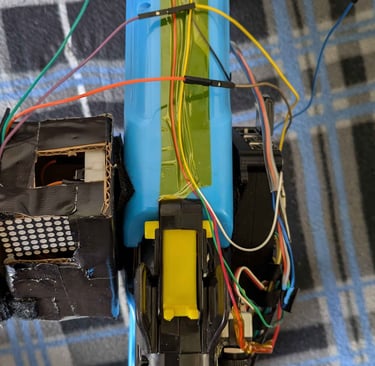
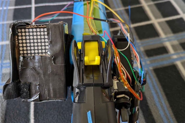
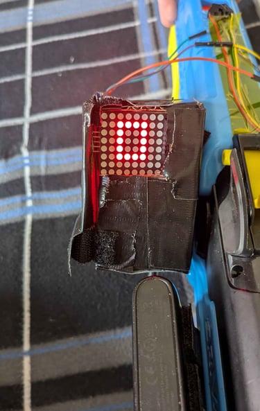
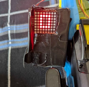
LED Matrix Display:
There is an LED Matrix display on the side of the gun that is controlled by an STM 32. The STM32 reads two inputs from the gun Pi that let it know when ammo has either left or entered the gun. The display shows the amount of ammo in the gun. It uses SPI to communicate with the STM board to display the custom-made numbers created. Additionally, the number zero on the LED Matrix will flash, catching the user’s attention when they run out of ammo. It is also important to note that, at the no ammo state, the STM32 communicates with the gun Pi to stop it from detecting “dry-fire” (no ammo left in the gun) shots.
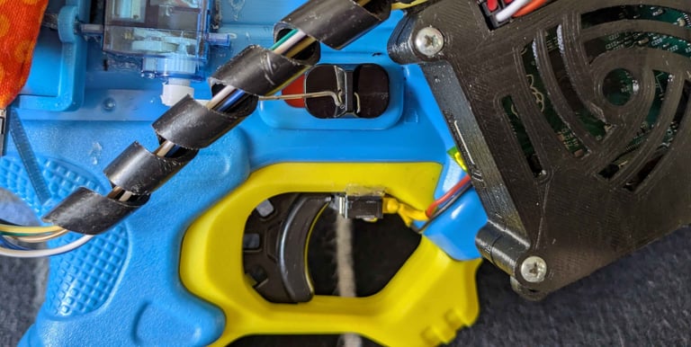
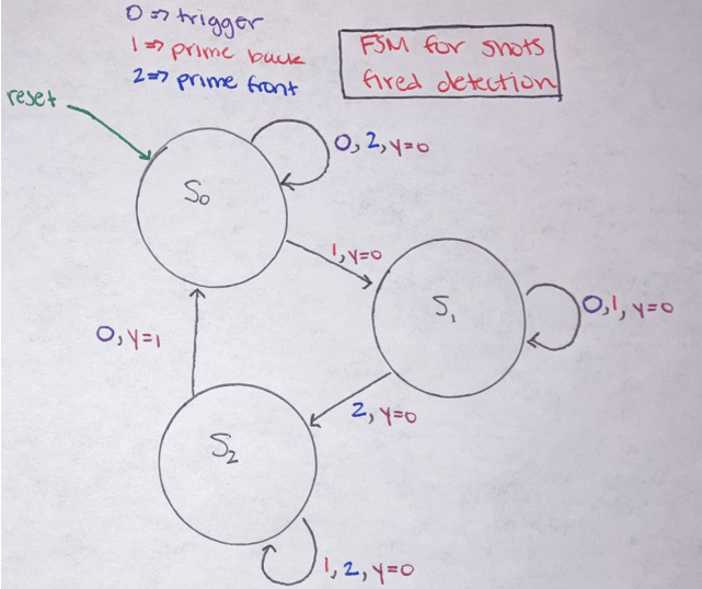
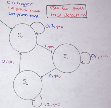
Shots Fired Tracking Switches:
The type of Nerf gun we used has a three-step process to fire a shot. To fire the user needs to pull the slider back, push it all the way forward, and then pull the trigger. The trigger can be pulled at any time in this process and not do anything if the other requirements are not met first. Pulling the trigger without a shot being fired would cause issues with the ammo tracking on the STM 32 and also with the data tracking on the target Pi (total shots fired and the shooting accuracy). To avoid this issue, we created a state machine that would go through these three stages and only detect a shot fired after the gun had been locked, loaded, and then fired.
1.
Shot Locked Switch:
The first sensor in this sequence is the one that detects when the gun enters a locked state. This sensor is located where the slider will hit once pulled all the way back. When the switch is hit by the slider, it will send a signal to the raspberry pi saying that the gun has been locked.


2.
Shot Loaded Switch:
The second sensor in this sequence is the one that detects when the gun enters a loaded state. This sensor is located where the slider will hit once pushed all the way to the front of the barrel. When the switch is hit by the slider, it will send a signal to the raspberry pi saying that the gun has been loaded and is primed to fire.


3.
Shot Fired Switch:
The last sensor in this sequence is the one that detects when the gun fires. This sensor is located on the trigger and is continuously hit by the trigger unless the trigger is pulled. When the trigger releases the switch, it will signal to the raspberry pi that the gun has been fired and return to the state waiting for the next locked signal.


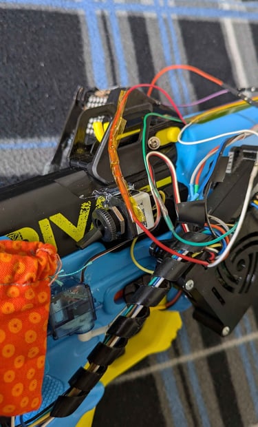
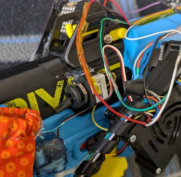
Free Fire vs. Target Mode Switch:
This Nerf gun has the capability to switch between target practice and a free fire mode. In free fire code, the gun only tracks how many times the user fired and displays just that. The user can change the mode at any time during use using the switch and it will reset their shots fired to 0. This switch is located on the right side of the gun. When the switch has a high signal, the gun is in free fire mode and when the switch has a low signal it is in target mode.
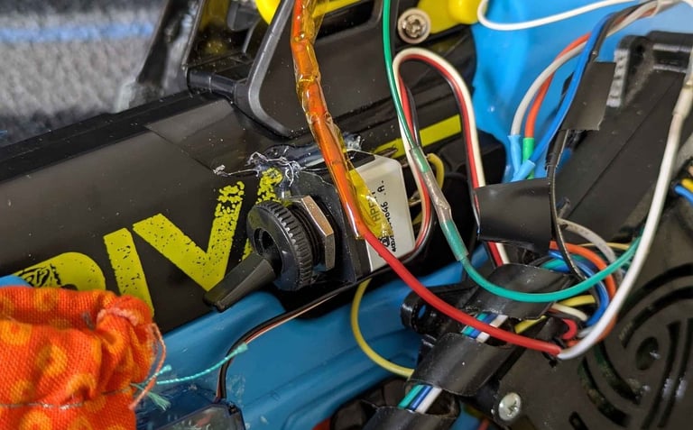
RFID Tag and Reader:
There is an RFID tag and reader on the side of the gun as well. This tag has an encoded password on it and when it is in contact with the RFID tag, it reads the password from the key using SPI and sends a signal to the Raspberry Pi on the gun to send a command to the Servo motor to unlock the trigger lock as long as the key is in contact.


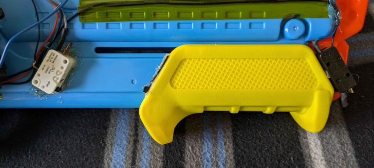
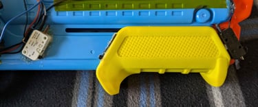
Servo Motor for Trigger Lock:
There is a servo motor on the right side of the gun that moves a wire a small distance to lock and unlock the trigger lock on the gun depending on the input it receives from the RFID tag.


Code:
Code for the Gun
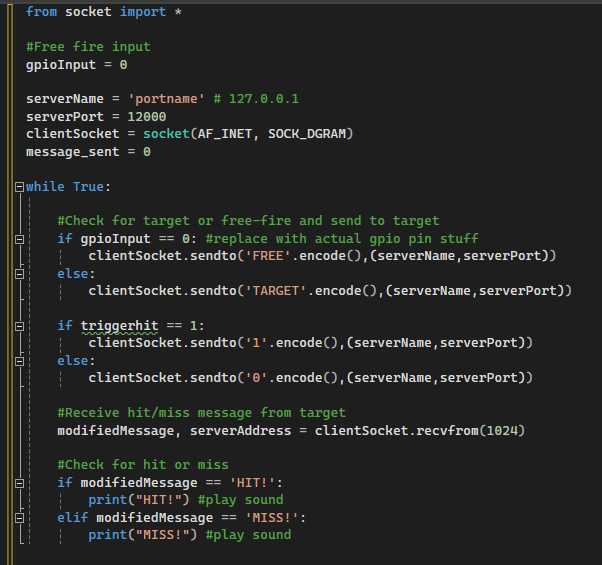
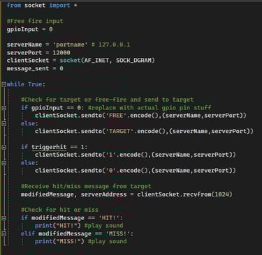
This code is the Client of the UDP and located on the gun. It tells the target which mode the user is in. It will send a message with the initial mode when turned on and will send an update each time the free-fire/target-fire switch is flipped. It will send a message of '1' if a shot was fired to let the target know each time that occurs. It then receives a message from the target stating whether the target was hit or missed and plays the associated sound. The trigger cannot be pulled if the RFID tag is not in contact with the Key and code not shown in the screenshot will not do anything if the gun is locked.
Finite State Machines and Diagrams with Logic for the Code for the Gun
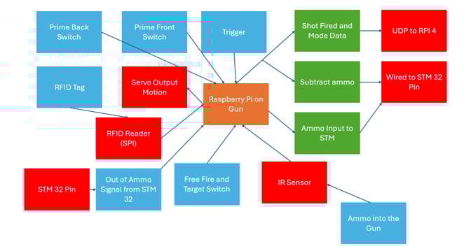
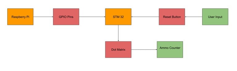
Block Diagram for Raspberry Pi 2
Code for the Target
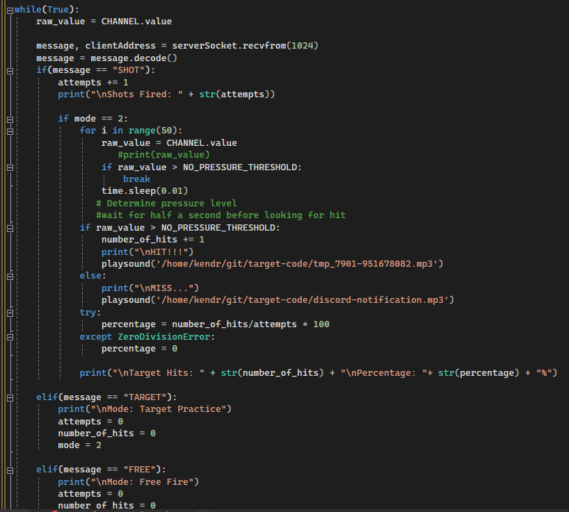
This code is the Server of the UDP and is run from within the target. All of the data the target is displaying is reset when the mode switch is flipped. If the target receives a message that a shot has been fired, it will add that to the total count of shots taken. While the target is in target mode, the target will display the number of shots, the number of hits, and the percentage of accuracy. It will also send a message back to the gun that there was either a hit or miss. If the program is in free fire mode, the target only outputs the number of shots taken.
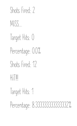
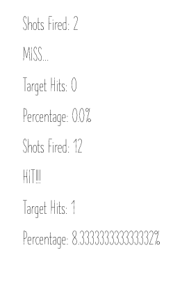
Example Output for Target Mode:
Finite State Machines and Diagrams with Logic for the Code for the Target
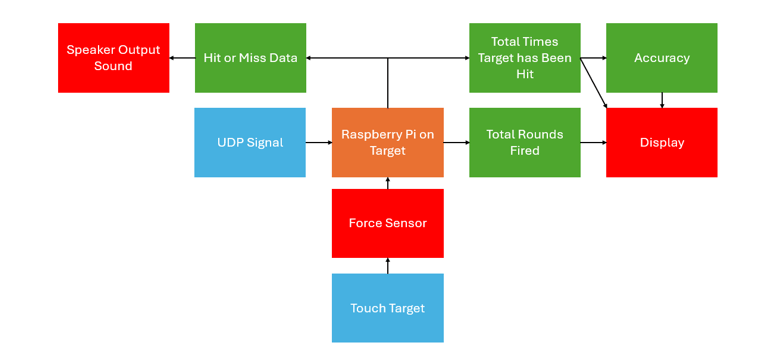
Block Diagram for the Raspberry Pi 4
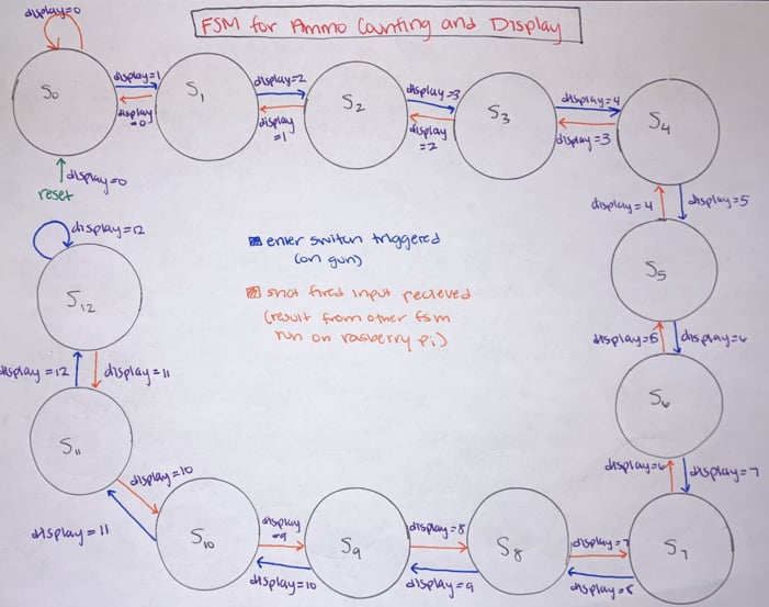
Code for the STM 32 Running the LED Matrix
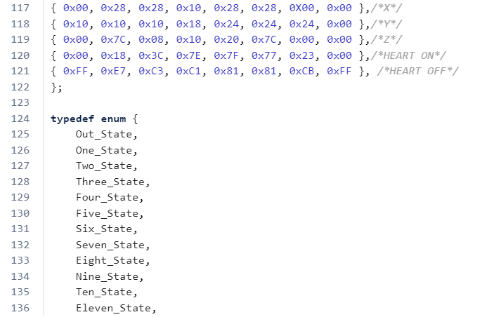
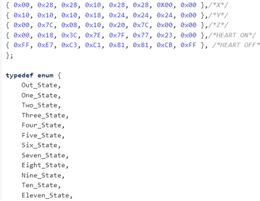
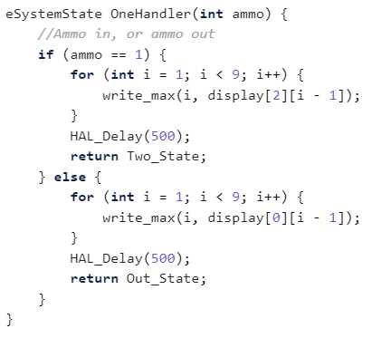
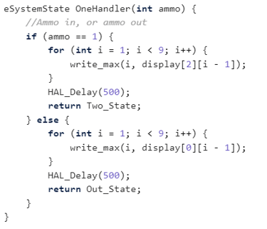
This code controls the LED Matrix displaying the ammo count of the gun. It employs a finite state machine for each possible number of balls in the chamber. If there is no ammo left in the gun, the matrix will flash a zero, otherwise the numbers stay constant and do not flash. If the IR Sensor sends a signal that a ball has been inputted, the state will switch to the one with one higher value and display the associated number. If the STM receives a signal hardwired from the Raspberry Pi on the Gun that a shot has been fired, the current state will go to one with one lower value and display that value. A maximum of 12 balls fit in the chamber so that is the highest state. If a discrepancy between the displayed value and actual number of balls in the gun, the user can empty the gun and then press the reset button to set the ammo count back to zero and reload the balls.